Starting April 2023 all EOS products are now available through Redox Tech
Environmental Professionals can use the EOS Design Tool for anaerobic bioremediation systems to select the best formulation in the right quantities.
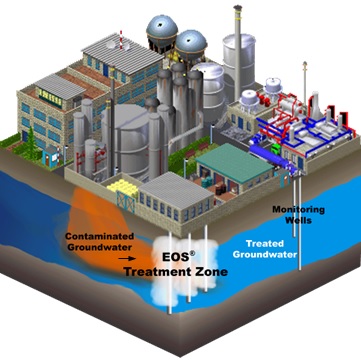
EOS Remediation, LLC (EOS) is the leading provider of bioremediation products that reengineer the groundwater environment for cost-effective, in situ treatment of groundwater, transforming contaminants into non-toxic end products. We developed the EOS® Design Tool to assist environmental professionals in the proper design of an EOS® enhanced anaerobic bioremediation project. The EOS® Design Tool uses science-based, site-specific data and design criteria, literature reference values, and potential safety factors to calculate the quantity of EOS® product required for your specific site.
EOS makes this software available at no cost to environmental professionals to guide the design of anaerobic bioremediation systems using EOS® emulsified oils. The design tool includes simple, easy to follow instructions with reference tables for certain input parameters. The design tool allows users to compare the efficiency of different EOS® products under specific site conditions. EOS® products may not be suitable for all applications. Prior to accessing the design tool, users should have already conducted a preliminary screening to determine if anaerobic bioremediation using emulsified oils is appropriate for the conditions at their site.
The design tool calculates the quantity of EOS® emulsified oil products and/or the bioaugmentation culture BAC-9 which is a microbial consortium of Dehalococcoides sp. enriched. If you are only interested in the bioaugmentation culture, click the “DHC Dosage” tab in the above menu. Otherwise, click the “Start” button below to proceed.
Disclaimer
The EOS® Design Tool, product sheets, brochures, instructions, technical advice, suggested recommendations and/or other information offered by EOS Remediation, LLC are provided as guidelines for the convenience of the Buyer only and should not be construed as a substitute for appropriate engineering and geologic design by qualified professionals. EOS Remediation, LLC is not a professional engineering firm and does not provide engineering design advice. Soil and other environmental conditions vary; therefore, the requirement and effectiveness of our products will vary according to the site specific conditions.
The EOS® design tool was written exclusively for the EOS® family of bioremediation products. Oil retention depends on aquifer characteristics and substrate properties. Be aware that generic products are constructed with different formulations/chemistries. Oil retention factors for polylactate esters and products containing ethyl lactate are often significantly different than for EOS® Products. Substrate distribution and treatment efficiency may be considerably lower than desired when products other than those of EOS Remediation are used. Your use of this software is subject to the terms of this disclaimer and is being provided "as is". By using this software, you agree to this disclaimer , the limitation of liability and terms of use described therein.
EOS Remediation, LLC. is licensed under US and international patents: US RE40,448 and RE40,734, EP 1315675, CA 2394068 and AU 782548, which are primary patents for the use of emulsified oils for groundwater bioremediation.
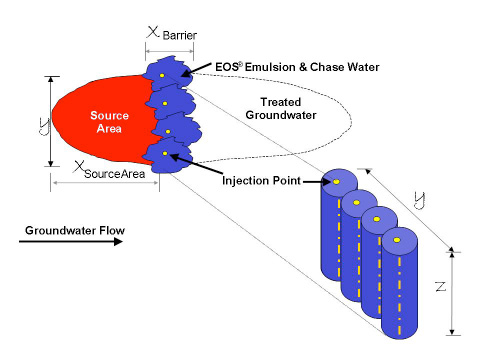
Source Area Treatment: EOS® can be distributed throughout a source area to reduce the contaminant mass flux out of the source area and to treat the contaminants over time. It is designed to treat both mobile dissolved contaminants and relatively immobile sorbed/residual contaminants. Addition of EOS® can rapidly reduce contaminant concentrations in the aqueous phase by partitioning of a portion of the solvent mass into the EOS® (i.e., sequestration). Biodegradation of the EOS® then stimulates anaerobic conditions and rapid biodegradation of solvents in the aqueous phase. As contaminants are slowly released by desorption from the aquifer matrix or by dissolution from residual DNAPL, EOS® will still be present to sustain anaerobic biodegradation processes.
Barrier Treatment: A barrier is the row of injection points designed to control/cut-off the downgradient migration of a contaminant plume. In many cases, the source of a contaminant plume is poorly defined or a plume is a result of multiple dispersed sources where source containment/reduction is not feasible. In other cases, it may be desirable to intercept a contaminant plume upgradient of a property boundary or a potential receptor. Under these conditions, EOS® can be injected in a permeable biobarrier configuration for plume treatment or plume containment
Emulsified and Water Mixable Oils Family
Emulsified oil products are engineered to optimize subsurface conditions that promote anaerobic bioremediation.
 is a nutrient-enriched, DoD-validated, food-grade oil/water emulsion designed to quickly stimulate microbial activity while providing long-term nourishment to enhance anaerobic bioremediation of chlorinated solvents, nitrates, perchlorate, energetics, acid mine drainage and other recalcitrant chemicals in contaminated groundwater (formerly 598B42).
 is a concentrated, low salt emulsion, formulated to minimize the dramatic spike of dissolved sodium (Na) in the aquifer that is caused by many other injectable remediation products. It is designed to enhance anaerobic bioremediation of chlorinated solvents, nitrates, perchlorate, energetics, acid mine drainage and other recalcitrant chemicals in contaminated groundwater.
 is a premium, food-grade oil/water emulsion designed to overcome the challenges of matrix diffusion. EOS XR gradually releases electron donors over decades to treat chlorinated solvents and other persistent contaminants that slowly diffuse out of clays, fractured rock and other low permeability zones (back-diffusion).
 is a food-grade oil/water emulsion that maximizes substrate value while enhancing anaerobic bioremediation of chlorinated solvents, perchlorate, energetics, acid mine drainage, oxidized metals and other recalcitrant chemicals in contaminated groundwater. It serves as a basic support for sites with established microbial communities, while maximizing substrate value.
 is a water-mixable vegetable oil based organic substrate to provide a lasting source of carbon for enhanced in-situ anaerobic bioremediation. It is shipped as a concentrate, simply mix with water to instantly create an injection friendly oil solution. Due to its high oil retention, EOS 100 is excellent for barrier applications and high velocity aquifers.
Our emulsified oils are part of the USDA BioPreferred Program. To achieve certification with the USDA BioPreferred Program, one of the components for bioremediation materials is to have at least 86% biobased content in the product. Each of our emulsified oil substrates goes above and beyond this standard.
For more information about EOS® products: http://www.eosremediation.com/product-overview/
% Oil: percentage of soybean oil in EOS® product (by weight)
e-/Kg (electron equivalent/Kg): total amount of electrons released per Kg EOS® Product
g EOS/mole DOC: inverse of moles of dissolved organic carbon (DOC) per EOS® product
% Fermentable Organic Substrate: percentage of fermentable organic in EOS ® product (by weight)
Barrier Design: Barriers are typically installed across the plume and perpendicular to groundwater flow. The width of an EOS® barrier (perpendicular to groundwater flow) should be wider than the contaminant plume to allow for uncertainties in the actual plume dimensions, variations in groundwater flow direction, and some permeability loss. When using EOS®, the permeability loss associated with the actual product injection is expected to be minor, therefore not considered in the calculations.
For a barrier design, the software requires the spacing between the injection wells ("x"), the anticipated width of the zone in which EOS® will be injected (perpendicular to groundwater flow, "y"), and the thickness of the treatment zone (“z”, difference between the maximum and minimum depth of contamination).
Source Area Design: For a source area design, the software requires the length (“x”), width (“y”), and thickness (“z”) of the proposed EOS® treatment area.
Total porosity (n) is the void volume/total volume x 100%.

Effective porosity (ne) is the porosity through which flow can occur. A thin film of water bound to soil particles by capillary forces does not move through the aquifer.
ne is always <= n
The following tables provide typical porosity and effective porosity values for different soil types:
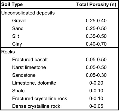
Source: Freeze and Cherry, 1979
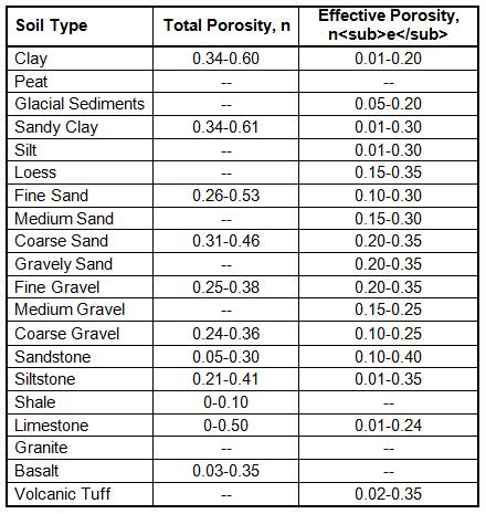
Source: Source: AFCEE, 1995
Soil bulk density:
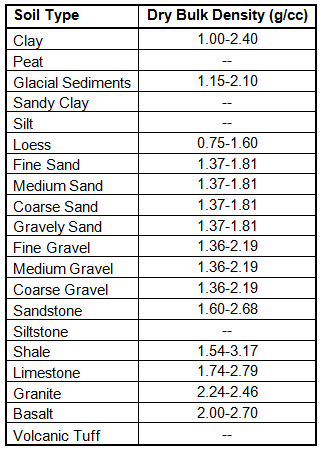
Source: AFCEE, 1995 after Wlaton, 1988; Domenico and Schwartz, 1990
Fraction of organic carbon (foc) is the mass of organic matter in soil divided by the total mass of soil. It can be thought of as the portion of the organic matter that is available to adsorb the organic contaminants of concern. Typical range for foc is between 0.0001 and 0.01.
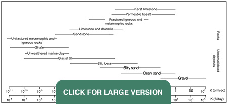
Hydraulic conductivity (K) is a property of soil or rock that describes the ease with which water can move through pore spaces or fractures. It is a coefficient that describes the permeability of soils (Freeze and Cherry, 1979):

The following table provides typical K values for different soil types:
Hydraulic gradient (i) is the change in water elevation (head; dh) divided by the distance (dx) between two points (Fetter, 1994):

You determine dh/dx from two head measurements using the equation:

Since dh/dx is negative, we ask you to enter -dh/dx in the EOS® Design Tool so that you can enter a positive number for convenience.
Seepage Velocity (Vx), is the average rate at which water is moving between two points:

If vx is less than 0.01 feet/day, the EOS® Design Tool will use 0.01 feet/day for vx.
Volumetric flow rate (Q) is the groundwater flow rate through the EOS® treatment zone and is estimated as:

If vx is less than 0.01 feet/day, the EOS® Design Tool will use 0.01 feet/day for vx.
Contact time (τ) is the average time a substance spends within a specified region of space. It is volume (V) and the volumetric flow rate (Q) in the mathematical relationship:

Contact time (τ) within the treatment zone will be controlled by the groundwater flow velocity (vx) and length of the treated zone along the direction of groundwater flow. At present, there is no reliable, all-inclusive method for determining the required contact time for effective treatment. Laboratory column experiments and field studies suggest a 1- to 3-month residence time should be sufficient in most cases.
The typical range is in between 60 to 180 days. A longer residence time should be used for:
- High sulfate loading
- High methane production
- “Unknown” high K layers that could cause short-circuiting through oil treated zone
- High contaminant concentrations
- High removal efficiency required
Based on the groundwater flow velocity (vx) and residence time (τ), the EOS® Design Tool will calculate the required contact length for a treated zone along the direction of groundwater flow as:

If “x” is less than 5 feet, the EOS® Design Tool will use 5 feet for “x”.
The Design Tool will default to the greater value between the calculated contact length and the value for “x” entered in Step 3, Section A: Treatment Area Dimensions.
Design life:
When selecting a design life for an EOS® application, users should be aware that the design spreadsheet assumes:
- All reactions go to completion during passage through the EOS® treatment zone;
- It is a perfect reaction stoichiometrically; and
- The EOS® application operates at 100% efficiency until the day when the organic substrate runs out. On that day, the treatment efficiency is assumed to drop to zero.
In practice, treatment efficiency will begin to decline as the EOS® is depleted from the more permeable/contaminated zones. Consequently, designers should include an appropriate factor of safety when selecting the design life.
In addition, designers should take into account: project cost, contaminant source(s) and concentrations, and remedial objectives when selecting a design life. For example, in some barrier projects, a 10-year design life has been used with the assumption that additional EOS® may need to be injected after five years.
Estimated total groundwater volume treated over design life (VDL) is the water volume that passes through the treatment zone during the lifetime of the EOS® application.
Barrier Design: For an EOS® barrier design, the EOS® Design Tool determines the total groundwater volume treated over the design life based on initial effective volume within the proposed barrier zone and the flow of groundwater into the barrier during the treatment period.
Source Area Design: For an EOS® source area treatment, the volume of water to be treated is determined based on the volume of groundwater within the treatment zone and the groundwater flow into the treatment zone during the treatment period.
EOS® ferments in the subsurface generating hydrogen and acetate. The hydrogen and acetate are used to support reductive dechlorination. However, hydrogen and acetate may also be consumed during biodegradation of naturally occurring electron acceptors such as oxygen, nitrate, sulfate, ferric iron, and manganese. As a consequence, designers should consider both the amount of contaminant to be reduced and the background electron acceptor load.
The amount of EOS® required to reduce a mass of dissolved contaminants and/or electron acceptors can be determined by calculating the stoichiometric hydrogen demand of the dissolved contaminants/electron acceptors.
In this section of the EOS® Design Tool, the designer is required to enter the concentrations of contaminants and other naturally occurring electron acceptors. The stoichiometric hydrogen demand of each analyte is then estimated.
Stoichiometric Demand is the mass ratio of contaminant or the naturally occurring electron acceptor to molecular hydrogen (H2) needed for reduction and is based on balanced chemical reduction equations. The EOS® Design Tool provides the stoichiometric demand for most contaminants and naturally occurring electron acceptors. For user added contaminates, the stoichiometric demand must be inputted and can be calculated by:

Hydrogen Demand is the stoichometric mass of hydrogen (H2) needed for reduction of contaminants or the naturally occurring electron acceptors.

In addition to the contaminants and electron acceptors entering the treatment zone, hydrogen can also be consumed in the EOS® treatment zone during: reduction of iron oxides and manganese oxides that may be present in the aquifer material; production of methane; and release of dissolved organic carbon (DOC). The ideal approach for estimating the iron and manganese demand is to directly measure the amount of bioavailable iron and manganese oxides in the aquifer material and determine the fraction of these oxides that will be reduced per year. Unfortunately, these data are not commonly available. An alternative approach is to calculate the iron and manganese demand based on the amount of dissolved iron and manganese released to the downgradient aquifer. This approach may somewhat under estimate the iron and manganese demand, but should be a reasonable approximation in most cases. Hydrogen and acetate that is not consumed by reductive dechlorination or electron acceptor reduction will be fermented to methane or released to the downgradient aquifer. As a consequence, additional substrate must be injected to account for any methane production and DOC released. Design Tool provides typical ranges for Fe+2, Mn+2, methane formed and DOC released.
Target Amount of DOC to Release

Organic contaminants will sorb to and desorb from organic matter naturally present in the aquifer. As a consequence, designers should consider the mass of sorbed contaminant mass in source area calculations. The concentration of the sorbed contaminant can be estimated by:

Default values for Koc taken from: US EPA, Superfund Section, APPENDIX K, Soil Organic Carbon (Koc) / Water (Kow) Partition Coefficients (Average Value Used)
Sorbed Contaminant Mass
The sorbed contaminant mass can be estimated by multiplying the estimated concentration of the organic matter in the soil, bulk density of the sediment and total volume of the treated area.
Users should be aware that the design tool calculations assume:
- All reactions go to completion during passage through the EOS® treatment zone;
- It is a perfect reaction stoichiometrically; and
- The EOS® application operates at 100% efficiency until the day when the organic substrate runs out. On that day, the treatment efficiency is assumed to drop to zero.
In practice, treatment efficiency will begin to decline as the EOS® is depleted from the more permeable/contaminated zones. Consequently, designers should include an appropriate safety factor for the design.
Stoichiometric Hydrogen Demand is the sum of the inputs (electron acceptors) and the sum of the consumption of hydrogen in the generation of Fe+2, Mn+2 and methane.
DOC Released

Where: g EOS/mole DOC is the inverse of moles of dissolved organic carbon (DOC) per g of EOS® product.
Substrate Requirement Based on Hydrogen Demand and Carbon Losses

For effective treatment, EOS® must be distributed throughout the treatment zone. However as EOS® migrates through the aquifer pore spaces, a portion is retained. For NAPLs, the oil is trapped in the aquifer pores as large globules, typically retaining 1 to 20 lb of oil per cubic foot of treated material. For EOS®, the small oil droplets coat the sediment surfaces, typically retaining between 0.1 to 0.5 lb of oil per cubic foot of treated material.
Effective Treatment Thickness (ze) is thickness of the transmissive zone (high K layers) that most emulsion moves through. The Cross-section below shows the vertical extent of contamination is around 45 feet and the thickness of the higher K zone is around 15 feet so the effective treatment thickness should be 33%.
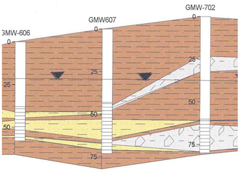
The EOS® Design Tool estimates the amount of oil required to treat an aquifer by multiplying the treatment zone volume by the oil retention in grams of EOS® per gram of sediment. For effective treatment, edible oil emulsions must be distributed throughout the treatment zone. Observed emulsified oil retention in a variety of sediments is provided below.
| Aquifer Material | Emulsion | Test Condition | Maximum Retention (lbs Substrate/lbs soil) |
Reference |
|---|---|---|---|---|
| Blended sand (7% silt + clay) | Emulsified Oil | Lab Column | 0.0054 | Coulibaly and Borden, 2004 |
| Blended sand (9% silt + clay) | Emulsified Oil | Lab Column | 0.0061 | Coulibaly and Borden, 2004 |
| Blended sand (12% silt + clay) (Coulibaly and Borden, 2004) | Emulsified Oil | Lab Column | 0.0095 | Coulibaly and Borden, 2004 |
| Clayey sand alluvium (Maryland Perchlorate Site, EOS®) | Emulsified Oil | Lab Column | 0.0037 | ESTCP, 2006 Borden, 2007 |
| Low K, weathered rock (sandy clay with remnant fractures) | Emulsified Oil | Field (estimate) | 0.0030 | Borden et al., 2007 |
| Coarse grained sand and gravel | Emulsified Oil | Field (estimate) | 0.0004 | Kovacich et al., 2007 |
| Medium grain sand | Emulsified Vegetable Oil | Lab Column | 0.0024 | Konzuk et al., 2006 |
| Blended 50/50 washed masonry and un-washed filed sand (5.4% silt +clay) | EOS 100 | Lab Column | 0.0225 | — |
| Un-washed field sand (23% silt +clay) | EOS 100 | Lab Column | 0.0322 | — |
| Washed masonry sand (3.4% silt + clay) | EOS 100 | Lab Column | 0.0049 | — |
The amount of EOS® required to treat an aquifer is determined by multiplying the width perpendicular to flow (y), effective vertical height of the treated zone (ze), thickness along the direction of groundwater flow (x), bulk density of the sediment, and oil retention by the aquifer material.
In many aquifers, the amount of EOS® required to coat the aquifer material is much greater than the amount of oil required for biodegradation and will control the total amount of oil that must be injected.
Design Safety Factor typically ranges from 1 to 2. It is typically 1 for source area treatment and 2 for barrier design.
Barrier Design: Barriers are typically installed across the plume and perpendicular to groundwater flow. The width of an EOS® barrier (perpendicular to groundwater flow) should be wider than the contaminant plume to allow for uncertainties in the actual plume dimensions, variations in groundwater flow direction, and some permeability loss. When using EOS®, the permeability loss associated with the actual product injection is expected to be minor, therefore not considered in the calculations. For a barrier design, the software requires the spacing between the injection wells ("x"), the anticipated width of the zone in which EOS® will be injected (perpendicular to groundwater flow, "y"), and the thickness of the treatment zone (“z”, difference between the maximum and minimum depth of contamination).
Source Area Design: For a source area design, the software requires the length (“x”), width (“y”), and thickness (“z”) of the proposed EOS® treatment area.

